We recently ran a comparison between two LTE Cellular systems on the same vessel and came to the conclusion that one system performed remarkably better than the other while the router hardware was the same, just the antennas were different, although they had the same power rating (9dB).
Antenna Radiation patterns
While radiation patterns are a very complex subject which relates more to dark magic in strangely padded rooms there are some relatively simple concepts that we can work with.
An isotropic antenna sends power equally in all directions. If the antenna has a gain, this power gets concentrated in a particular direction. This is known as EIRP.
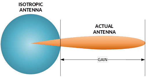
Higher gain antennas achieve extra power by focusing on a reduced area; thus, the greater the gain, the smaller the area covered (measured in degrees of beamwidth). Antenna gain and beamwidth always are inversely proportional.
EIRP is relevant in the horizontal as well as the vertical plane, where the isotropic antenna radiates like a perfect ball and the actual high gain antenna radiates like the beam of a flashlight.
What is Beamwidth?
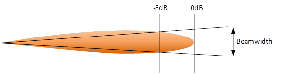
The beamwidth, or half power beamwidth, is the beamwidth between two points where the power is 50% lower (3 dB) than the maximum radiation power in the center of the beam.
For example, an omnidirectional antenna with an 11 dBi gain and a horizontal beamwidth of 360°, has a vertical beamwidth of 7.15°
The actual vertical beamwidth of the omnidirectional antenna is usually even smaller than the calculated result due to manufacturing precision.
If we take the above example we now know that an 11 dBi omnidirectional antenna had a vertical beamwidth of about 7°, which compared to the pitch and roll of a ship, depending on its size and sea conditions, does not leave us much to work with. As soon as the ship’s motion exceeds half the vertical beamwidth (3.5° above or 3.5° below the beam center) the signal will already have lost half its power.
A ship rolls about 10° in both directions on moderate seas. While this might be less for large ships (>100m) smaller boats will quickly experience degraded connectivity as soon as there is some distance from shore and Cellular Tower and the actual gain of the antenna becomes important.
Making a fatter Donut
As the shape of the radiation pattern resembles a donut we actually need to have a thicker donut so that the vertical beamwidth increases and the ship’s pitch and roll angles stay within the antenna’s radiation sweet spot.
To achieve this we can do two things: lower the horizontal angle or decrease the overall gain of the antenna. As it is an omnidirectional antenna we have to keep the horizontal beamwidth to 360°. This leaves us with teh only option to lower the antenna gain.
Omnidirectional Antenna Gain vs. Beamwidth:
- Gain: 11 dBi – Vertical beamwidth: 7.15°
- Gain: 10 dBi – Vertical beamwidth: 9.00°
- Gain: 9 dBi – Vertical beamwidth: 11.33°
- Gain: 8 dBi – Vertical beamwidth: 14.26°
- Gain: 7 dBi – Vertical beamwidth: 17.96°
- Gain: 6 dBi – Vertical beamwidth: 22.61°
- Gain: 5 dBi – Vertical beamwidth: 28.46°
- Gain: 4 dBi – Vertical beamwidth: 35.83°
- Gain: 3 dBi – Vertical beamwidth: 45.11°
- Gain: 2 dBi – Vertical beamwidth: 56.79°
- Gain: 1 dBi – Vertical beamwidth: 71.49°
- Gain: 0 dBi – Vertical beamwidth: 90.00°
As the vertical beamwidth has increased we also notice a significant loss in gain. 3dBi less means half the power … and by extension also half the distance or half the throughput which may result in losing connection alltogether due to insifficient signal strength.
Sailing between a rock and a hard place
If the above sounds familiar to you then you know that tradeoffs will need to be made. Either go for less gain and more freedom to roll and pitch or keep the gain but allow for less roll and pitch motion. Unless if you have a stabilized platform on which you could mount the antennas there isn’t much that can be done except for increasing the power of the radio but that might be frowned upon by the local authorities and cellular providers.
There is a solution to this problem though, and it has been thoroughly tested in a maritime environment enabling much greater pitch and roll while maintinaing signal strength, … more information in the next post or get in touch if you can’t wait.